Friday, June 28, 2013

Trouble Shooting Diedrich ignition, a documentation of a support call

Trouble Shooting ignition, a documentation of a support call a log of the call

Q:

Let’s test the Dungs vacuum sensor. If you remove the clear cover, you can turn the dial and change its sensitivity. Mark where it currently sits before you move the dial. It should be set at 0.3 but try moving it to 0.2 or 0.1 and seeing if your roaster will light. If it does, that will tell us that you have an airflow restriction somewhere in your roaster. If not, we may need to replace the vacuum sensor. The little plastic/rubber tube that comes off the Dungs valve and connects to the tube that hangs down in your blower housing should also be checked to make sure it’s completely clean. Let me know what happens.
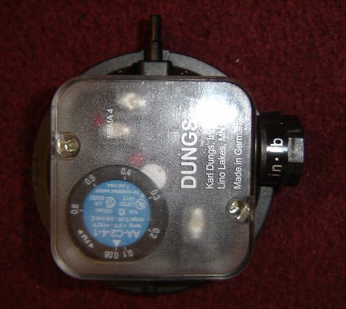
 Dungs Vacuum sensor

A:

We actually connected the 2 brown wires together in the sensor today as the fault finding guide says to do. But I have done as you asked and still nothing. I tried it at 0.1 and 0.08 still no spark

I disconnected the black tube too and I can blow or suck through it fine

Q:

You also checked the aluminum tubing that hangs down in the blower compartment? If you’re sure everything is clean, we can try replacing the vacuum sensor and seeing if that fixes the problem. I’ve attached our guide to narrowing down where the issue may be. Do you already have this guide? (see below) It says if you’re not hearing the clicking, to check to make sure your high limit unit is functioning. We should try to rule out as much as possible before we replace any parts.

A:

This is the one we used, we go through it a few times. This is the guide that says to take the vacuum sensor out of the loop by connecting the 2 brown wires, we did that and it made no difference, so surely it is on the sensor? I checked the tube, blown through it and sucked through it. The roaster is clean we are fussy about this. The automatic machine reset the high limit when you power on the roaster. I am not how else to reset it. I am not sure where the Watlow thing is positioned.( Turns out it is next to the Abbey Electrical Igniter, with jumpers labeled

Q:

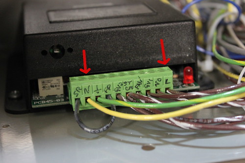
With the blower on, take a continuity reading between commonly open and common to make sure we’re getting power there. If yes, then the ignition controller may need to be replaced, if no power, then the vacuum sensor needs to be replaced. Let me know what you find. Check for power at these two connections on your Abbby ignition controller. AbbeyElecticalIgnitionController

A:

Did this and use the wiring diagram to determine the startup was stuck at the vacuum sensors. Looks like shorting out the wires did not help. When we blew into the pipe it then worked. Found a blockage in the outside chimney.

Lessons from Trouble shooting the IR12 Ignition problems

In an effort to share the knowledge gained, and to document for our own use here is a trouble shooting summary of how we solved the Ignition problems. We used a number of documents that are available at different places on the net, so there is a list:
There are also some videos we posted under the equaffee youtube account

So essentially what did we do?

We removed the side panels to expose the Abbey Electrical Ignition controller and Dungs vaccum sensor on the right. Using a meter we tested that current was coming in as per the Fx4 diagrams. The using the diagram we check that each item from the startup was happening as required. During this process we identified that the vacuum meter was not feeding back a ready message. We then disconnected the silicon tube that was going to the aluminium tube in the fan hosing and blow into it so that the vacuum meter identified that there was a vacuum.

This then solved the problem, well at least pointed us to the reason, soon we were roasting great coffee. Sounds easy but took days.


I have listed their logic below on how the ignition controller fires.

Normal sequence of events for the “Air Proving” Abbey Ignition Control.
  1. The Drum switch is turned on by the operator.
  2. The Gas switch is turned on by the operator.
    • 24vac transformer energizes providing 24vac via 2amp fuse to Abbey control board terminals (L)-(N), Abbey ignition module (2)-(10), Watlow hi limit terminals (L)-(N).
    • The Watlow hi limit is a fail safe device and takes a second to energize. A short “chirp” will be heard until the Watlow energizes. After energizing 24vac will be at Watlow (NO)-(N) and Abbey ignition module (2)-(6). The Abbey LED will light.
    • When the Abbey ignition module sees 24vac at (2)-(6) and NOT 24vac at ((2)-(9) “Air proving” is established and the Abbey ignition module energizes (2)-(7), “Call for fan”. This is what lights the blue lamp alerting the operator to now turn on the Blower.
  3. The Blower switch is turned on by the operator.
    • The air vacuum switch provides 24vac to the Abbey ignition module (2)-(9).
    • After a pre-purge time the Abbey LED will flash, the spark should be heard, and 24vac is provided to the Abbey ignition module terminals (2)-(8), pilot valve. The Abbey ignition module is waiting for flame verification before energizing terminals (2)-(5), main valve. When flame verification is detected the LED will return to steady on.
  4. The Abbey ignition module will retry igniting 2-3 times. After 2-3 retries the Abbey ignition module locks out and the Blower and Gas switches will have to be turned off and the above sequence repeated.
  5. NOTE: When the Abbey ignition module locks out the LED will resort to a slow flash to indicate an error. The flashes, example: 3 times will be separated by a short pause and then flash 3 times again to indicate a “3” error. Refer to the Abbey literature for a more detailed explanation of LED operation and error codes. Pages 12-14 of 17 of the attached - could not attach